
Dell-Ray and I are currently building an Arduino-powered screwdriver antenna controller. Check out our current status on Facebook!
Screwdriver Antenna Controller
by
Johnny McCown
3/24/2013
Background:
Almost 6 years ago, a good friend of mine, Patrick, gave me his Ameritron SDA-100 Screwdriver Antenna. The antenna uses a switch in the cab of the car to move it up and down (the standard basic setup). Inside the antenna is a motor similar to that found in a hand drill. When you press the switch in the up position, it drives the motor which pushes the coil of the antenna upward, and the reverse happens when you push the switch in the down postion. As you tune the antenna up and down, you should listen to your frequency to see when it gets the strongest. Once you are close, you could move the radio to CW/AM/RTTY to transmit since you verified the SWR on a SWR meter. This could be time consuming, and most of all dangurous, if driving.
Over a year ago, I told my good friend, Dell-Ray, that I would like to build a controller with some memory presets that would work with the reed switch in the antenna to position it. We started to look at the different designs of other screwdriver antenna controllers to see what we preferred so we could have a starting point. While we did like memory presets, units with that option tend to be quite big. Also, most units do not communicate with the radios. Actually, I have not seen any that will talk with the radio.
Our Design Ideas:
> Be able to control the antenna manually
> Controller would be able to tune automatically from presets or the current freq. on the radio
> Could be able to talk with my ICOM 706MIIG, and then as needed with other radios
> Use an Arduino so other people could easily work with this project and customize it
> Be able to build this contoller for less than what is sold on the market
> Use this project to help us get better at CNC Routers (for etching PCB), and Eagle CAD
If you would like to look at the Arduino code; to get an idea of how it works, to use it on your project or copy our project you may find the source code at( my fiend’s GitHub page):
https://github.com/lospheris/AntennaTuner/blob/master/README.md
Other links:
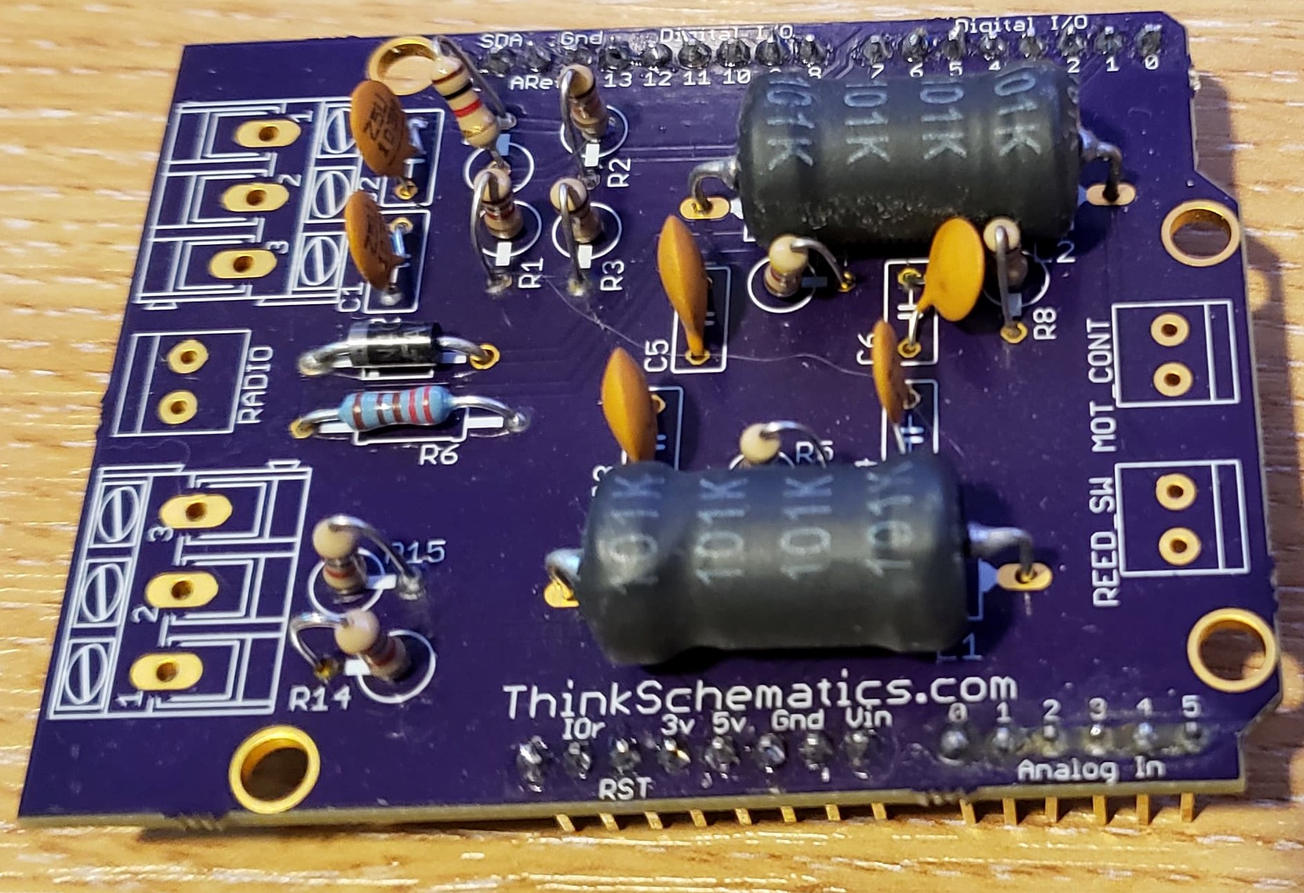
I had a set of boards made at OshPark. They are considered Alpha Testing stage, if you would even consider that.
https://oshpark.com/profiles/ThinkSchematics
Current Status of Project:
Please check out our Facebook page for the latest photos and updates. Dell has been working on the programming. We have a prototype that is waiting to be field tested. Also, I have been changing the PCB in Eagle CAD to make it more moduler, and I have also been trying to find a way where we can fit the PCB in a project box that would not be the size of the radio.
Updates:
3 Mar 19: Talking with a few people recently on FaceBook about this project, I figured I would make some updates. As you can see from the OshPark website, I had some boards made Feb 16. If I remember correctly, I made this board using KiCad, I am trying to not use EagleCAD, because of the limitations. I assembled one set of boards, but never tested it. I have a tendency to start more projects before finishing the one I am on. Though in my defense, is a project ever done? There is always room for improvement. I will try to ass a parts list to this, so you will know what I used. Most of my parts I get from places like AllElectronics.com…if I don’t have it in my parts bin!
28 July 2013: Well so far today Dell-Ray has figured out the problem with the sensor, it looks like it was not updating the screen. He fixed that! Now my next request/question to him was “How do we make it so the Arduino keeps the turn count of the antenna once the controller loses power?“ It looks like this unit consumes a lot of power, so we might have to turn it off so that it does not drain the car battery that it is installed in.
13 June 2013: Looks like the new LCD works on the screwdriver antenna control unit running off of bat power. Next i will make sure the relay works then check to see if the control unit will count the turns as the antenna goes up and down.
22 Apr 2013: Last week I started soldering on wires for VCC and COM, then I did a “smoke test”. Well the smoke test failed. Well it turns out that we accidently installed a 7812 (12vDC output) instead of a 7805 (5vDC output) voltage regulator. Devices such as screens, displays drivers, ICs, and microcontrollers do not like it when you give them too much voltage.
27 July 2012: Last night I work on the Antenna Control Unit, as I video chat with my Father-In-Law. We found that the trace from T1’s emitter to ground was bad, and needed a jumper wire. Also, we found that D7 and D6 were looking for HIGH inputs when S1 was activated, though the way we set up the board the input was suppose to be a LOW when S1 was activated. Dell-Ray and I are currently taking a look at the Sensor input that is sent to digital PIN 2 on the MCU. Dell is great at coding / debugging.
Credits:
Dell-Ray took my ideas and has done some great programming. At first, Dell created the PCB on Eagle CAD, but with our changes and ideas, I have been updating the board and working on its layout.