
This is an old post of mine about the electronics in my CNC. At first I was having problems getting motors to turn, and then latter I was having problems getting the limit switches to work. Let me know if you have any basic questions about EMC2, I might have the answer.
My first CNC Router
The last few weeks I have been building a CNC Router. My wife bought me a Bosch Colt 1hp router from Amazon for my birth day. Then shortly after that I bought the hardware/plans kit, electronics, and 5 start .5” screws. Once the parts that I bought came in I went to a local wood store and bought a sheet of 3/4 inch MDF. I also went to hardware store and bought some aluminum angle, unfortunately they were not thick enough so I had double/triple them up so they would be the correct thickness. So, the first weekend after receiving all of these parts I built the table for the CNC and the gantry. The gantry is the device that moves along the table and holds the router. Soon you will see some photos and see what I am talking about. Well I ran into some more snags…I bought the wrong nuts that would go onto the large .5 inch screws, so some of the nuts will be replaced collars, and three of them will be replaced with Anti-back lash nuts. As I wait for this additional hardware I have been working on the electronics portion. I have taken an old computer that I have, and installed Ubuntu onto it, if you do not know Ubuntu is a Linux OS. The nice part about this is that it is FREE!! Also to control the CNC I am use a well-established program called EMC2, also FREE!! After buying a CNC you have to do something to keep money in your pocket…it will be expensive no matter whom you purchases it from.
Well back to the electronics…I am having a few problems getting a stepping motor to turn. Currently I am looking for help with my problem, if you can help me figure out why I can’t get my stepper to turn I would appreciate it. First to start off I connected the controller to the computer, then the driver was connected to the controller, and last the stepper motor and power supply were connected to the controller. Throughout this process I was checking all of the voltages. I have tried this setup with a different driver, but still need to try it with a different stepper.
Here is what I am using for my electronics:
C10R10 Parallel Port Interface Card from www.cnc4pc.com
Microstep Driver CW230
Stepper Motor PN: SW60HT86-2008BF-U2 run in Bipolar Parallel
Power supply is a 36 volt DC out / 8 amps, with 110/220 VAC input, currently set for 220 VAC
The configuration is as follows:
On the Parallel port Interface Card
Com is set to 5 VDC (pin 2-3)
Pins 2-9 are pull down (setting is pin 1-2)
Pins 2-9 are output pins (setting is pin 1-2)
Pin 2 is connected to CP- of the Driver (these voltage were checked using a O-scope)
Com is connected to CP+ and CW+ of the driver
Pin 3 is connected to CW- of the driver (its output is 5vDC in one direction & 0vDC in the other)
On the Driver
Reset + no connections
Reset – no connections
B- is connected to wires green and orange of the stepper motor
B+ is connected to wires white and brown of the stepper
A- is connected to wires yellow and black of the stepper
A+ is connected to wires red and Blue of the stepper
Grd is connected to the COM of the 36 VDC power supply
VCC+ is connected to the +V of the 36 VDC power supply
The Switch settings of the Driver are:
1 -> up
2 -> down
3-8 are set to up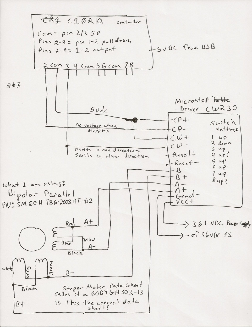
Click HERE to see my configuration file for EMC2 (you might want to open this file using Notepad or any other text editor).